Most maps allow us to specify the location of points on the Earth's surface using a grid coordinate system. In a two-dimensional map, this coordinate system uses simple geometric relationships between the perpendicular axes of a grid to define spatial location (Figure 2.5). Two types of spatial coordinate systems are currently in use: the geographical coordinate system and the rectangular coordinate system.
Geographical Coordinate System
A geographical coordinate system measures location from only two values, despite the locations being described for a three-dimensional surface. These values used to define location are both measured relative to the Earth's polar axis. The two measures used in the geographic coordinate system are called latitude and longitude. Both of these measures are expressed as an angle measured in degrees (°), minutes ('), and seconds (").
Latitude measures the north-south position of locations on the Earth's surface relative to a point found at the center of the Earth (Figure 2.6). This central point is also located on the Earth's rotational or polar axis. The equator is the starting point for measuring latitude. The equator has a value of 0°. A line of latitude or parallel of 30° North has an angle of 30° north of the plane represented by the equator (Figure 2.7). The maximum value that latitude can attain is either 90° North or South. These lines of latitude run parallel to the rotational axis of the Earth.
Longitude measures the west-to-east position of locations on the Earth's surface relative to a circular arc called the Prime Meridian (Figure 2.6). The position of thePrime Meridianwas determined by international agreement to be a line of longitude aligned with the location of the former astronomical observatory in Greenwich, England. Because the Earth's circumference is approximately circular, it was decided to measure longitude in degrees. The number of degrees found in a circle is 360. The Prime Meridian has a value of zero degrees. A line of longitude or meridian of 45° West has an angle of 45° west of the plane represented by the Prime Meridian (Figure 2.7). The maximum value that a meridian of longitude can have is 180°, which is the distance halfway around a circle. This meridian is called theInternational Date Line. Designations of west and east are used to distinguish where a location is found relative to the Prime Meridian. For example, all the locations in North America have a longitude that is designated west.
Rectangular Coordinate System
Rectangular coordinate systems define a location on two-dimensional surfaces, such as maps. Most topographic maps use a specific rectangular coordinate system called the Universal Transverse Mercator (UTM) grid. The Universal Transverse Mercator grid system uses the meter (m) as its basic unit of measurement. UTM also uses the Transverse Mercator projection system to model the Earth's spherical surface onto a two-dimensional plane.
The UTM system divides the world's surface into 60 six-degree longitude-wide zones that run north to south (Figure 2.8). These zones start at the International Date Line and are successively numbered eastward. Each zone stretches from 84° North to 80° South. In the center of each of these zones is a central meridian. Location is measured in these zones from a false origin determined relative to the intersection of the equator and the central meridian for each zone (Figure 2.8). For locations in the Northern Hemisphere, the false origin is 500,000 meters west of the central meridian on the equator. Coordinate measurements of location in the Northern Hemisphere using the UTM system are made relative to this point in meters in eastings (the longitudinal distance) and northings (the latitudinal distance). The point defined by the intersection of 50° North and 9° West would have a UTM coordinate of Zone 29, 500000 m East (E), 5538630 m North (N) (see Figures 2.8 and 2.9). In the Southern Hemisphere, the origin is 10,000,000 m south of the equator and 500,000 m west of the central meridian. The location found at 50° South and 9° West would have a UTM coordinate of Zone 29, 500000 m E, 4461369 m N (remember that northing in the Southern Hemisphere is measured from 10,000,000 m south of the equator - see Figures 2.8 and 2.9).
The UTM system has been modified to make measurements easier to understand. This modification divides the six-degree-wide zones into smaller pieces or quadrilaterals, eight degrees of latitude tall. Each of these rows is labeled, starting at 80° South, with the letters C to X consecutively and with I and O being omitted (Figure 2.8). The last row, X, differs from the other rows and extends from 72° to 84° North latitude (twelve degrees tall). Each of the quadrilaterals or grid zones is identified by its number/letter designation. In total, 1200 quadrilaterals are defined in the UTM system.
The quadrilateral system allows us to define locations more precisely using the UTM system. For the location 50° North and 9° West, the UTM coordinate can now be expressed as Grid Zone 29U, 500000 m E, 5538630 m North. Each UTM quadrilateral is further subdivided into many 100,000-by-100,000 m zones. These subdivisions are coded using a system of letter combinations, with each two-letter combination not repeated within 18° of latitude and longitude. Within each of the 100,000 by 100,000 m squares, one can specify location to one-meter accuracy using a 5-digit easting and northing reference system.
The UTM grid system is displayed on all United States Geological Survey (USGS) and National Topographic Series of Canada (NTS) maps. On USGS 7.5-minute quadrangle maps (1:24,000 scale), 15-minute quadrangle maps (1:50,000, 1:62,500, and standard-edition 1:63,360 scales), and Canadian 1:50,000 maps, the UTM grid lines are drawn at intervals of 1000 meters, and are shown either with blue ticks at the edge of the map or by full blue grid lines. On USGS 1:100,000 and 1:250,000 scale maps and Canadian 1:250,000 scale maps, a full UTM grid is shown at 10,000-meter intervals. Figure 2.10 describes how the UTM grid system can determine a location on a 1:50,000 National Topographic Series of Canada map.
Global Positioning Systems
Determination of location in field conditions was once a difficult task. It often required using a topographic map and recognizing landscape features to roughly estimate the location. However, technology has now made this task very simple and precise. Global Positioning Systems (GPS) can calculate one's location anywhere on our planet with an accuracy of between 5 to 0.3 m (16 to 1 ft) (Figure 2.11). GPS systems consist of two parts: a GPS receiver and a network of satellites orbiting our planet. Radio transmissions from these satellites are broadcast continually. A GPS receiver must receive the signal of at least three satellites to calculate a two-dimensional position (latitude and longitude). With four or more satellites, the GPS receiver can determine an individual's three-dimensional position (latitude, longitude, and altitude). The heart of GPS technology is the ability of the transmitting satellites to keep extremely precise time and position information. GPS satellites measure time with atomic clocks that are accurate to within one second every 70,000 years.
GPS was first developed for military use. Initially, the military thought this location technology would be extremely useful for navigation on land, at sea, and in the air. The technology was applied to other tasks, including troop location monitoring and weapon guidance. The first solar-powered GPS satellite was launched in 1978, and by 1980, a network of six satellites was in operation. Today, 31 satellites make up the GPS space network orbiting the Earth at an altitude of around 20,000 km above us. These satellites orbit the Earth twice a day, traveling at about 11,000 kph.
In the mid-1980s, the technology became available for civilian use. At first, the US military deliberately degraded the accuracy of civilian GPS units for national security reasons. This degradation was turned off in May 2000. Additional accuracy and reduced receiver costs have led to the rapid expansion of civilian use. GPS has proven to be an extremely valuable tool in forestry, agriculture, mineral exploration, and other field activities.
GPS is now being combined with various computerized technologies to increase its usefulness. Some handheld GPS units are being merged with computers to record and store location and other related field data in digital form for later use. Once back in the office, the data stored in the unit can be transferred into a Geographic Information System for processing and analysis. GPS is also used to display and track an individual's location on software-driven digital maps. In these units, mapping software is combined with GPS to allow users to monitor their position and movement on topographic or street maps. These real-time navigation systems are now available in cars, smartphones, and handheld tablet computers (Figure 2.12).

FIGURE 2.5 A grid coordinate system defines the location of points from the distance traveled along two perpendicular axes from some stated origin. In the example above, the two axes are labeled X and Y. The origin is located in the lower left-hand corner. The unit distance traveled along each axis from the origin is shown. In this coordinate system, the value associated with the X-axis is given first, followed by the value assigned to the Y-axis. The location represented by the star has the coordinates 7 (X-axis), 4 (Y-axis). Image Copyright: Michael Pidwirny.

FIGURE 2.7 Measurement of latitude and longitude on the Earth. Latitude is measured relative to a point found at the center of the polar axis. Measurements of latitude range from 0 to 90°. Latitudes greater than zero are recognized as being either north or south of the equator. Longitude is measured relative to the equator plane and the Prime Meridian. Measurements of latitude range from 0 to 180°. Longitudes greater than zero are identified as being either west or east of the Prime Meridian. Image Copyright: Michael Pidwirny.

FIGURE 2.8 The UTM system also uses a grid system to break the Earth up into 1200 quadrilaterals. To keep the illustration manageable, most of these zones have been excluded. Designation of each quadrilateral is accomplished with a number-letter system. The six-degree-wide zones are numbered along the bottom, starting at 180 degrees West longitude, from 1 to 60. The twenty vertical rows are assigned letters C to X, with I and O excluded. The letter C begins at 80° South latitude. Note that the rows are 8° of latitude wide, except for the last row X, which is 12° wide. According to the reference system, the bright green quadrilateral has the grid reference 29V (note that the west-east coordinate is given first, followed by the south-north coordinate). This grid zone lies between 56 ° and 64° North latitude and 6° and 12° West longitude. Image Copyright: Michael Pidwirny.

FIGURE 2.9 The following illustration describes the characteristics of the UTM zone "29" found between 12 and 6° West longitude. Note that the zone has been split into two halves. The half on the left represents the area found in the Northern Hemisphere. The Southern Hemisphere is located on the right. The blue line represents the central meridian for this zone. A location's measurements for this zone are calculated relative to a false origin. This origin is located 500,000 meters west of the central meridian in the Northern Hemisphere. The Southern Hemisphere UTM measurements are determined relative to an origin located at 10,000,000 meters south and 500,000 meters west of the equator and central meridian, respectively. Image Copyright: Michael Pidwirny.

FIGURE 2.10 The top left-hand corner of the "Tofino" 1:50,000 National Topographic System of Canada map is shown above. The blue lines and associated numbers on the map margin are used to determine the location through the UTM grid system. Abbreviated UTM 1,000-meter values or principal digits are shown by numbers on the map margin that vary from 0 to 100 (100 is given the value 00). At each corner of the map, two principal digits are expressed in their full UTM coordinate form. On the image, we can see 283000 m E. and 5458000 m N. The red dot is found in the center of the grid, defined by principal numbers 85 to 86 easting and 57 to 58 northing. A complete UTM grid reference for this location would be 285500 m E. and 5457500 m N. Information on the map margin (not shown) also tells us that the area displayed is in Grid Zone 10U, and that the 100,000 m squares BK and CK are located on this map. Image Source: Natural Resources Canada - Toporama.
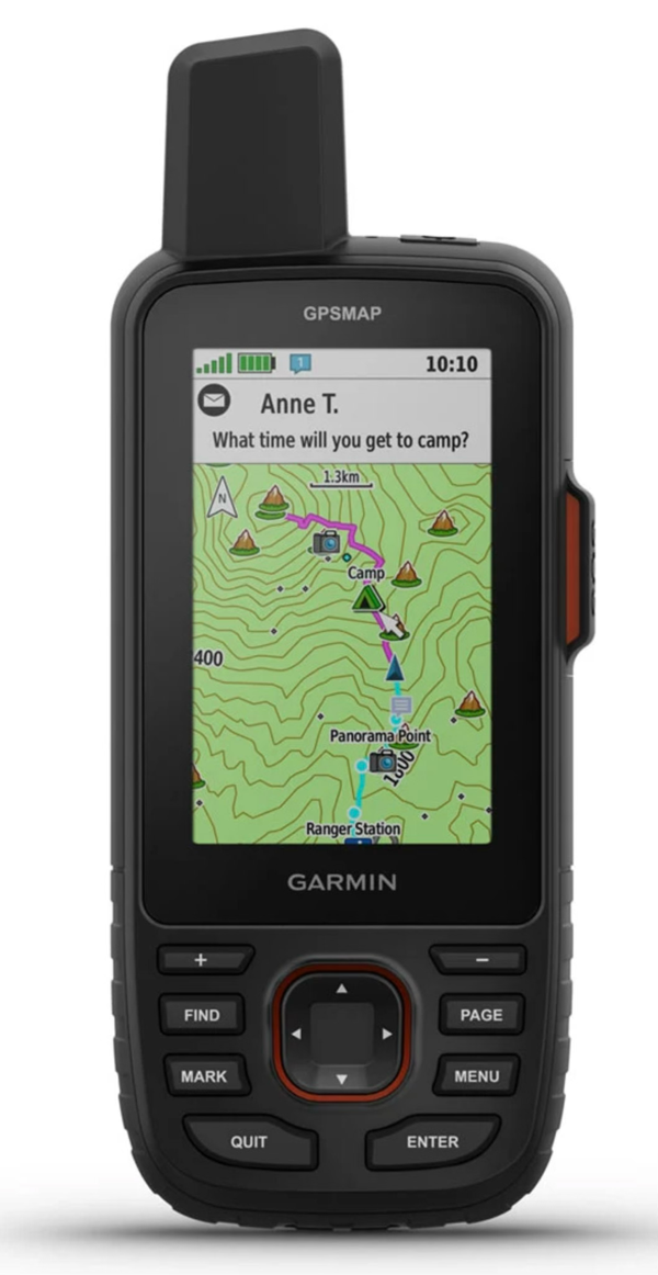
FIGURE 2.11 GPS receivers can determine latitude, longitude, and elevation anywhere on or above the Earth's surface from the signals transmitted by a number of specialized satellites. These GPS units can also be used to reveal direction, distance traveled, and determine routes of travel in field situations. Image Courtesy of Garmin Ltd.


FIGURE 2.6 Lines of latitude or parallels are drawn parallel to the equator (shown in red) as circles that span the Earth's surface. These parallels are measured in degrees. There are 90 angular degrees of latitude from the equator to each pole. The equator has an assigned value of 0°. Latitude measurements are also defined as being either north or south of the equator to distinguish the hemisphere of their location. Lines of longitude or meridians are circular arcs that meet at the poles. There are 180 degrees of longitude on either side of a starting meridian known as the Prime Meridian (shown in blue). The Prime Meridian has a designated value of 0°. Longitude measurements are also defined as west or east of the Prime Meridian. Image Copyright: Michael Pidwirny.
FIGURE 2.12 Garmin’s Drive™ 52 GPS can be loaded with detailed software maps for North America, Africa, Asia, Europe, Australia, and South America specially designed to assist vehicle travel. Image Courtesy of Garmin Ltd.